33+ current transformer block diagram
Improves Light Load Efficiency avoiding transformer acoustic noise. A Very Useful Blog About Electrical Electronics Engineering Technology Electrical Wiring- EE-Calculator EE Q-A EE Notes Motors Power System Control.

Solid State Relays Static Relays Relay Current Transformer Output Device
04 06 Nm.

. Each terminal block will accept one 10-18 AWG wire. 10 4 Ventilation 8 and safe load feeders 3RA71 A. TNY279 functional block diagram Source.
The SE-330 is an advanced ground-fault and neutral-grounding resistor monitoring relay that is compliant with Rule 10-302 of the 2018 Canadian Electrical Code Part I CE Code. Robert Tong joined onsemi in 2008 and is currently the senior vice president and general manager of the Advanced Solutions Group ASG responsible for business group strategy long-term product roadmaps and organization to ultimately drive gross margin and operating income. 1952 Chevrolet 31003604 relay diagram.
Like other power supplies an SMPS transfers power from a DC or AC source often mains power see AC adapter to DC loads. A block diagram is a type of electrical drawing that represents the principle components of a complex system in the form of blocks interconnected by lines that represent their relation. The basic concept remains the same you just need to arrange a heat sink for higher voltage and current.
With the advent of ring main units incorporating SF6 circuit breakers and isolators protection of distribution transformers can now be provided by overcurrent trips. Power Integrations During ON state current flows from D to S. Figure below shows the output characteristics of the NMOS transistor with showing the current sink region.
With the ENC28J60 two pulse transformers and a few passive components are all that are required to connect a microcontroller to an Ethernet network. SEPARATE OVER CURRENT PROTECTION IS REQUIRED TO BE PROVIDED IN ACCORDANCE WITH THE CANADIAN ELECTRICAL CODE. A current clamp uses a current transformer with a split core that can be easily wrapped around a conductor in a circuit.
Senior Vice President and General Manager Advanced Solutions Group. Here diode D5 andD6 is used as reve rse-current protection diode that don t allow the battery current to flow towards the supply section and diode D7 is for reverse polarity protection. It is the simplest form of electrical drawing as it only highlights the function of each component and provides the flow of process in the system.
If there is only two number it means there is no multiplier Then you just read the value of the first two numbers in picofarads. Figure shows the current sink circuit based on NMOS transistor. Built-in safety protection improved transient response.
When the first two numbers are multiplied with the multiplier the resulting value is the value of the capacitor in picofarads. 49 for R 0 33. Figure 1 HRC fuses.
A switched-mode power supply switching-mode power supply switch-mode power supply switched power supply SMPS or switcher is an electronic power supply that incorporates a switching regulator to convert electrical power efficiently. This power supply is only enough for powering one channel and for stereo applications double the current ratings of the transformer diodes and fuses. Voltage transformer or potential transformer.
SaveEmail Interactive Block Diagram worksheets Save custom parametric search filters. 011 421 33 790-2910. Current Mode Control Scheme.
BPM is used to decouple internal power supply and to decide global limiting value of current from drain to source by appropriate choice of capacitor between BPM and S. A 40-40 unregulated dual supply for powering this amplifier project is shown below. V GS â V TH then the transistor work as a current sink.
A typical application circuit using the device is shown in Figure 1-2. This is a common method used in portable current measuring instruments but permanent installations use more economical types of current transformer. From Figure it can be seen that if V DS is less than the gate overdrive voltage ie.
When pressed it completes the circuit to ground pulls the plunger down on the relay and makes contact with the H terminal which supplies power to the horns. With this setup the magnitude of current flow through 100Kilometer transmission line is reduced considerably thereby reducing the power loss during transmission. The output transformer matches the high impedance audio signal high voltage but low current.
Power supply for this project TIP 142 147 Internal diagram and pin out. For example tripping controlled by time limit fuses connected across the secondary windings of in-built current. The output transformer steps down the 348 VAC primary voltage to 11 VAC at the secondary and speaker jack for a -316x signal voltage reduction but the signals current is stepped up by the output transformer 316 times current gain factor of 316.
The power transformer is usually operated in full load because it is designed to have high efficiency at 100 load. Maximum feed breaker size of 30 Amps. Tighten terminal blocks to 35 to 5 in-lbs.
Mounting Diagram and Dimensions. The ENC28J60 consists of seven major functional blocks. An internal current limit state machine adaptively adjusts the.
The first two numbers describe the value of the capacitor and the third number is the number of zeros in the multiplier. As the short circuit current density J sc magnitude increases with a reduction of the band-gap as 12398E g eV and is illustrated in Fig. Ground for the relay is thru the mount to the firewall and ground to the horn is thru its mount or a separate ground wire.
You can also build 6V DC 9V 12V 15V etc by using proper transformer capacitor and voltage regulator. A simple block diagram of the ENC28J60 is shown in Figure 1-1. A plots of current density and band gap for a A current density of a p-n junction solar cell under short-circuit conditions and B voltage of a p-n junction solar.
Difference between Power Transformer and Distribution Transformer. Go back to contents. This circuit mainly consists a step down Transformer a Full wave bridge rectifier and a 5V voltage regulator IC 7805.

Pin On Circuit Diagram
3 Phase Current Transformer Wiring Diagram Collection Electrical Wiring Diagram Diagram Electrical Panel Wiring
2
2
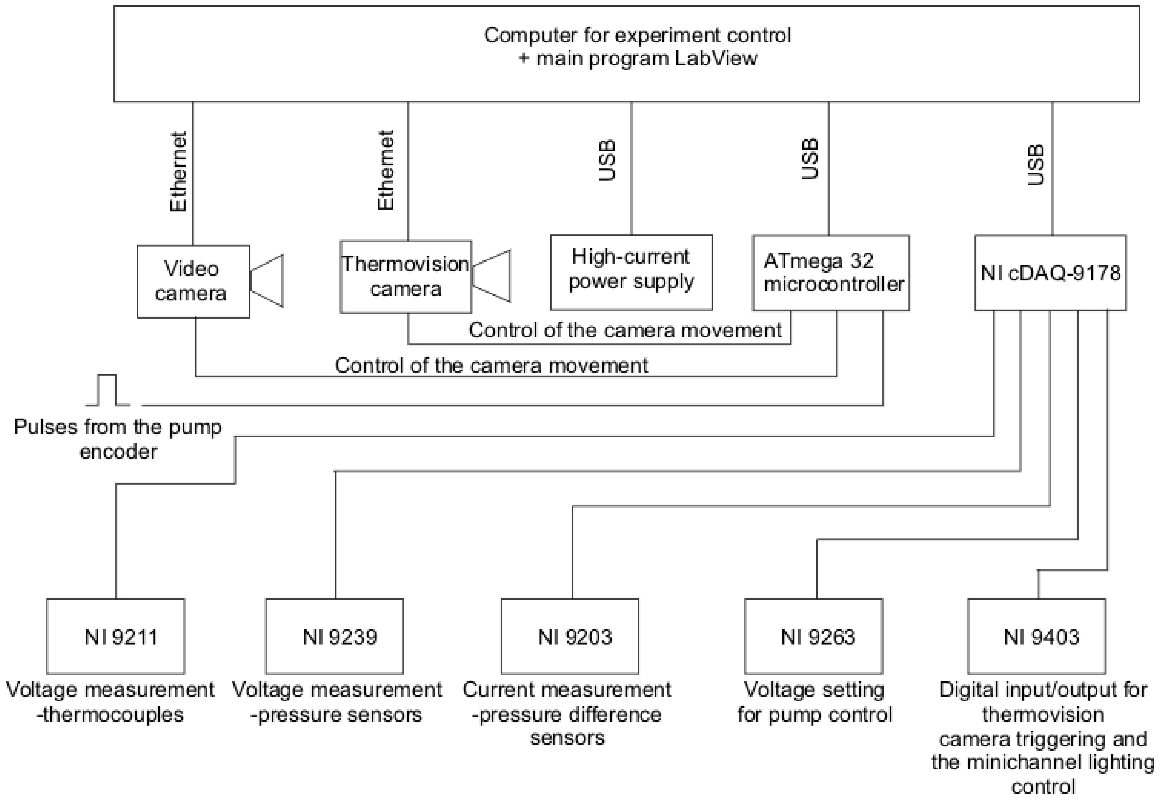
Energies Free Full Text Heat Transfer Coefficient Identification In Mini Channel Flow Boiling With The Hybrid Picard Trefftz Method Html
2

Pin On Knowledge

Electrical Transformer Symbols Single Line Transformer Symbols Electrical Transformers Transformers Electrical Circuit Diagram

Many Ways To Increase Current Transformer Of Power Supply Current Transformer Power Supply Circuit Power Supply

Useful Electronic Things Panosundaki Pin

Development Of Fast And Hybrid Charger For Lithium Ion Batteries In Light Weight Electric Vehicles Sabarimuthu 2021 International Transactions On Electrical Energy Systems Wiley Online Library
2
2
2

Electrical Systems Ct And Vt Comparison And Connection Connection Diagram Comparison
2

3 Phase Current Transformer Wiring Diagram Collection Electrical Transformer Wiring Diagram New T Current Transformer Transformers Electrical Circuit Diagram